Hardware notes
Schematics
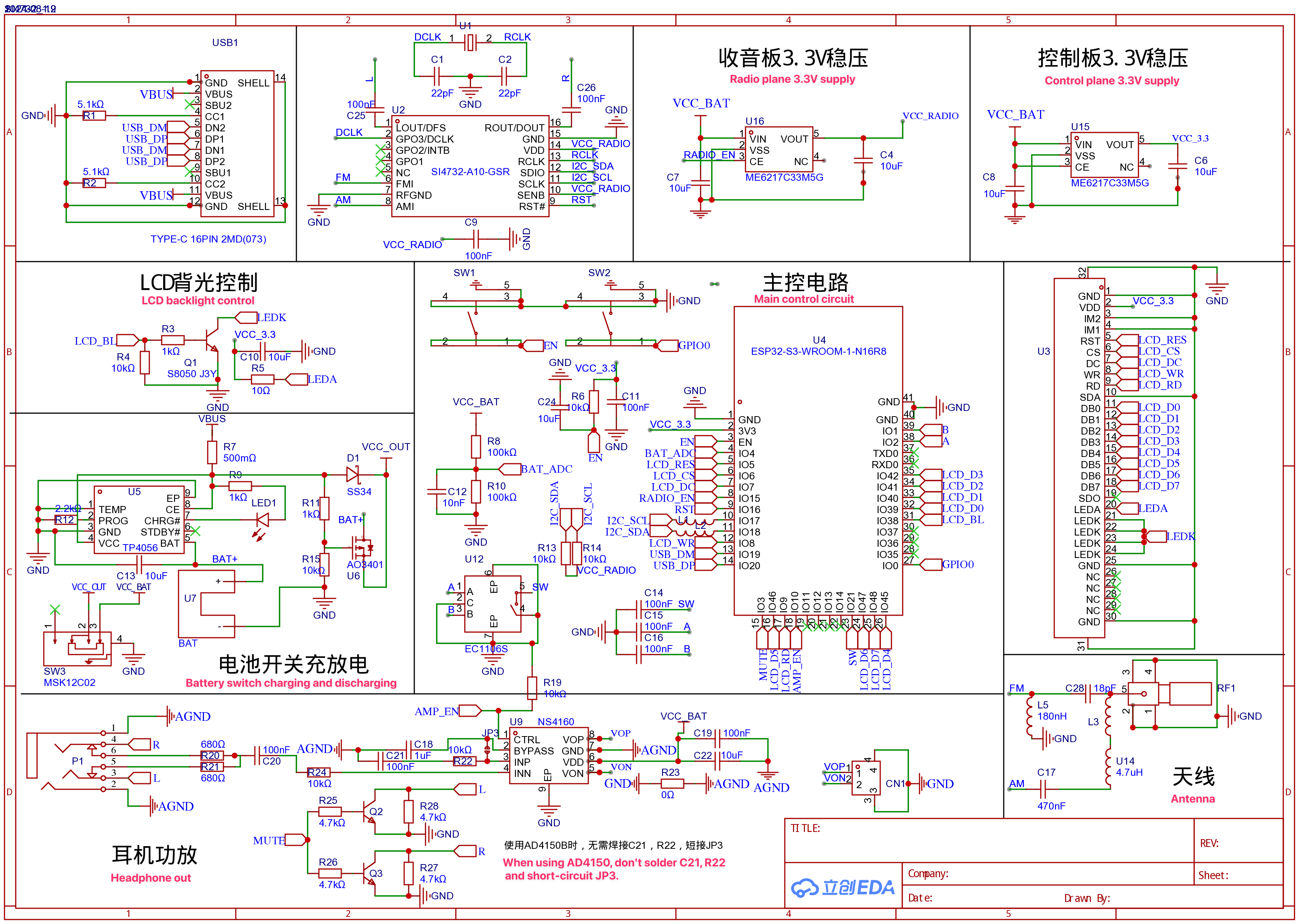
The original schematics, BOM and Gerber files can be found at https://oshwhub.com/sunnygold/esp32s3-si4732-shou-yin-ji. A copy of the files is available at https://github.com/esp32-si4732/esp32-si4732-oshwhub
No schematics available for other PCB versions currently sold, but you can find a brief overview here.
Datasheets
Pinout
The pinout table is shown below.
The relevant columns are ESP32-S3-WROOM-1 “Pin Name” and “ATS-Mini Sketch Pin Definitions”
ESP32-S3-WROOM-1 |
ESP32-S3-WROOM-1 |
ATS-MINI Sketch |
TFT_eSPI |
xtronic.org |
Comments |
|---|---|---|---|---|---|
1 |
GND |
GND |
|||
2 |
3V3 |
VCC_33 |
|||
3 |
EN |
EN |
RST Button |
||
4 |
IO4 |
VBAT_MON |
BAT_ADC |
Battery monitor |
|
5 |
IO5 |
TFT_RST |
LCD_RES |
||
6 |
IO6 |
TFT_CS |
LCD_CS |
||
7 |
IO7 |
TFT_DC |
LCD_DC |
||
8 |
IO15 |
PIN_POWER_ON |
RADIO_EN |
1= Radio LDO Enable |
|
9 |
IO16 |
RESET_PIN |
RST |
SI4732 Reset |
|
10 |
IO17 |
ESP32_I2C_SCL |
I2C_SCL |
SI4732 Clock |
|
11 |
IO18 |
ESP32_I2C_SDA |
I2C_SDA |
SI4732 Data |
|
12 |
IO8 |
TFT_WR |
LCD_WR |
||
13 |
IO19 |
USB_DM |
USB_D- (CDC Port) |
||
14 |
IO20 |
USB_DP |
USB_D+ (CDC Port) |
||
15 |
IO3 |
AUDIO_MUTE |
MUTE |
1 = Mute L/R audio |
|
16 |
IO46 |
TFT_D5 |
LCD_DS |
||
17 |
IO9 |
TFT_RD |
LCD_RD |
||
18 |
IO10 |
PIN_AMP_EN |
AMP_EN |
1 = Audio Amp Enable |
|
19 |
IO11 |
NC |
Spare |
||
20 |
IO12 |
NC |
Spare |
||
21 |
IO13 |
NC |
Spare |
||
22 |
IO14 |
NC |
Spare |
||
23 |
IO21 |
ENCODER_PUSH_BUTTON |
SW |
Rotary encoder SW signal |
|
24 |
IO47 |
TFT_D6 |
LCD_D6 |
||
25 |
IO48 |
TFT_D7 |
LCD_D7 |
||
26 |
IO45 |
TFT_D4 |
LCD_D4 |
||
27 |
IO0 |
GPIO0 |
BOOT button |
||
28 |
IO35 |
NC |
Used for OSPI PSRAM |
||
29 |
IO36 |
NC |
Used for OSPI PSRAM |
||
30 |
IO37 |
NC |
Used for OSPI PSRAM |
||
31 |
IO38 |
PIN_LCD_BL |
TFT_BL |
LCD_BL |
Backlight control |
32 |
IO39 |
TFT_D0 |
LCD_D0 |
||
33 |
IO40 |
TFT_D1 |
LCD_D1 |
||
34 |
IO41 |
TFT_D2 |
LCD_D2 |
||
35 |
IO42 |
TFT_D3 |
LCD_D2 |
||
36 |
RXD0 |
NC |
GPIO44 |
||
37 |
TXD0 |
NC |
GPIO43 |
||
38 |
IO2 |
ENCODER_PIN_A |
A |
Rotary encoder A signal |
|
39 |
IO1 |
ENCODER_PIN_B |
B |
Rotary encoder B signal |
|
40 |
GND |
GND |
|||
41 |
EPAD |
GND |
LILYGO T-Embed SI4732
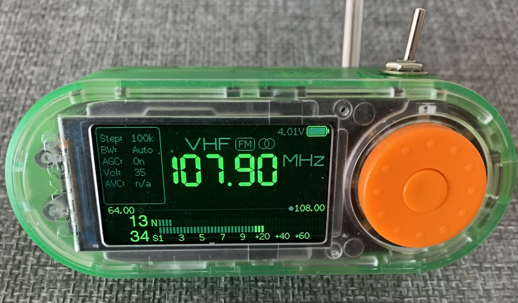
Impressions so far:
Due to the lack of a power switch, the stock firmware uses deep sleep, triggered by a long press, but it still drains the battery. The ATS Mini firmware already uses the long-press gesture for other purposes, so there is no way to turn the receiver off.
The reset button is external, and the boot button is combined with the encoder button. This makes triggering bootloader mode much easier, but it also means that to reset the receiver settings, you have to press and hold the encoder button right after powering the receiver on, not before.
The display is connected via SPI, but the MISO pin is used for different purposes. This means the display controller registers are write-only.
The display color palette is a bit off, so the themes look different.
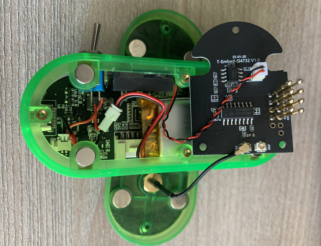
There are separate FM and AM antenna connectors on the SI4732 board.
The encoder is nice, but the push-and-rotate gesture is harder to use.
There is no headphone jack.
The speaker is on the top.
The antenna connector on the back cover can be used as a stand to tilt the receiver back.
It is highly recommended to do a little hardware mod and install a physical power switch (without it you won’t be able to switch the receiver off after you flash the ATS Mini firmware):
Links:
https://lilygo.cc/products/t-embed-si4732 - product page
https://github.com/Xinyuan-LilyGO/T-Embed/blob/main/schematic/ - schematic
https://github.com/Xinyuan-LilyGO/T-Embed/tree/main/examples/SI4735_Shield - stock firmware source code
https://github.com/Xinyuan-LilyGO/T-Embed/blob/main/firmware/SI4735_Shield_250308.bin - stock firmware binary