User Manual
Main screen
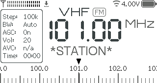
RSSI meter (top left corner), also serves as a mono/stereo indicator in FM mode (one/two rows).
Settings save icon (right after the RSSI meter). The settings are saved to non-volatile memory after 10 seconds of inactivity.
Bluetooth icon (right after the save icon). Different colors indicate the connection status.
Wi-Fi icon (top right area near the battery). Different colors indicate the connection status.
Battery status (top right corner). It doesn’t show the voltage when charged, see #36. The only indication that the battery is charging is the hardware LED on the bottom of the receiver, which turns ON during charging.
Band name and modulation (VHF & FM, top center). See the Bands table for more details.
Info panel (the box on the left side), also Menu. The parameters are explained in the Menu section.
Frequency (center of the screen).
FM station name (RDS PS) or frequency name (right below the frequency). A frequency name appears for some popular frequencies like FT8, SSTV, CB channels, or a shortwave schedule. Can also display current menu option using a bigger font when the Zoom Menu setting is enabled.
Tuning scale (bottom of the screen). Can be replaced with additional RDS fields (RT, PTY) when extended RDS is enabled, or RSSI/SNR graphs in Scan mode.
Alternative UI
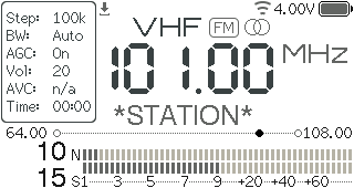
The differences are:
Stereo indicator is on the right side of the band and mode (VHF & FM).
Tuning scale (right under the station name). Numbers on the left & right sides are the band limits.
S/N Meter (in dB). The range is 0…127 and the visual indicator linearly displays this range.
RSSI & S-Meter (the number is in dBµV, the meter is in S-points). Please note that the RSSI range is also 0…127 (no negative values) and according to these tables any values below S4 on HF (rssi < 4) and below S7 on VHF (rssi < 2) are bogus. Thus it is very far from being precise, and also depends on the antenna impedance.
Both meters can be replaced with additional RDS fields (RT, PTY) when extended RDS is enabled, or RSSI/SNR graphs in Scan mode.
Controls
Controls are implemented through the encoder knob:
Gesture |
Result |
|---|---|
Rotate |
Tunes frequency, navigates menu, adjusts parameters. |
Click (<0.5 sec) |
Opens menu, selects. |
Short press (>0.5 sec) |
Volume shortcut in VFO mode, context-dependent action in other modes. |
Long press (>2 sec) |
Sleep on/off. |
Press and rotate |
Direct frequency input mode, fine tuning in Seek mode. |
Direct frequency input mode
Press and rotate the encoder to select the step (digit or “half-digit”).
Rotate the encoder to adjust the frequency.
Use short press to align frequency to the current step.
To exit the mode, click the encoder or wait for a couple of seconds.
Wi-Fi
The Wi-Fi mode (2.4GHz only) can be used for the following purposes (for now):
Time synchronization via NTP (Network Time Protocol).
Download the EiBi shortwave schedule.
Viewing the receiver status (frequency, RSSI/SNR, volume, battery voltage, etc).
Viewing the Memory slots with saved frequencies.
Manage the receiver settings.
There are a couple of modes:
Off (default)
AP Only - Access Point mode. The receiver creates its own access point called
ATS-Miniand starts the web server on http://10.1.1.1.AP+Connect - Access Point mode + try to connect to one of the three configured access points. If the connection succeeds, the receiver will synchronize the time every 5 minutes and start the web server on both http://10.1.1.1 and a dynamic IP address it got from the configured access point.
Connect - try to connect to one of the three configured access points, start the web server on a dynamic IP, then synchronize the time every 5 minutes.
Sync Only - same as Connect, but Wi-Fi will be disabled after a successful time synchronization.
Initial configuration:
Enable the AP Only mode (the receiver will briefly display its 10.1.1.1 IP address).
Connect to the
ATS-Miniaccess point from your phone or computer. There is no internet connection available on this access point. When connecting from a phone, it might be necessary to switch off the mobile data connection and any VPN/firewall software.Open a browser and visit the following URL: http://10.1.1.1. The status web page should open. Alternatively, you can try the mDNS address <atsmini.local> in your browser.
Click the
Configlink. Here you can configure up to three access points the receiver will try to connect to, add optional login and password to protect the settings page, and set a time zone and other settings. EnableScan Hidden SSIDsonly if one of the configured access points does not broadcast its network name; leaving it off makes Wi-Fi connection faster.After that, switch the Wi-Fi mode to AP+Connect or Connect (the receiver will briefly show its new dynamic IP address it got from a configured access point).
Now connect your phone/computer to the same access point and open the new URL to check whether the receiver connected to the internet.
From now on you can switch the modes as you want and connect to your receiver either via the ATS-Mini internal access point (if enabled, mostly useful when there are no access points around), or via an external access point and a dynamic IP address. The receiver will always listen on the mDNS address <atsmini.local>.
Hint
When on the go, you can set up a mobile Wi-Fi hotspot on your smartphone and use it to connect the receiver to the internet.
Schedule
The receiver can download the EiBi shortwave schedule and use it to display broadcasting stations, allowing you to quickly tune to them. Here’s how it works:
The schedule only needs to be downloaded once via Wi-Fi. It will be stored in the receiver’s flash memory so it doesn’t need to be fetched every time the device powers on.
To display scheduled stations correctly, the receiver’s clock must be set. The simplest and most battery-preserving way is to configure a Wi-Fi internet connection and then switch it to Sync Only mode. The UTC offset setting doesn’t matter, as the receiver syncs via NTP in UTC. A less reliable alternative is to use RDS CT, but this requires finding a station that broadcasts UTC time (not local time).
Once set up, the receiver will display station names currently broadcasting on specific frequencies (only scheduled times are considered; days of the week are ignored for now).
You can quickly jump between stations using the Seek mode (marked by a clock icon). To switch between modes, short press the encoder while in Seek mode.
Reset
To reset the receiver settings (current band, frequency, favorite stations, downloaded schedule, etc):
Switch off the receiver
Press and hold the encoder
Turn on the receiver
Release the encoder after the
Resetting Preferencesmessage appears
Bands table
Name |
Min frequency |
Max frequency |
Default mode |
|---|---|---|---|
VHF |
64 MHz |
108 MHz |
FM |
ALL |
150 kHz |
30000 kHz |
AM |
11M |
25600 kHz |
26100 kHz |
AM |
13M |
21500 kHz |
21900 kHz |
AM |
15M |
18900 kHz |
19100 kHz |
AM |
16M |
17400 kHz |
18100 kHz |
AM |
19M |
15100 kHz |
15900 kHz |
AM |
22M |
13500 kHz |
13900 kHz |
AM |
25M |
11000 kHz |
13000 kHz |
AM |
31M |
9000 kHz |
11000 kHz |
AM |
41M |
7000 kHz |
9000 kHz |
AM |
49M |
5000 kHz |
7000 kHz |
AM |
60M |
4000 kHz |
5100 kHz |
AM |
75M |
3500 kHz |
4000 kHz |
AM |
90M |
3000 kHz |
3500 kHz |
AM |
MW3 |
1700 kHz |
3500 kHz |
AM |
MW2 |
495 kHz |
1701 kHz |
AM |
MW1 |
150 kHz |
1800 kHz |
AM |
160M |
1800 kHz |
2000 kHz |
LSB |
80M |
3500 kHz |
4000 kHz |
LSB |
40M |
7000 kHz |
7300 kHz |
LSB |
30M |
10000 kHz |
10200 kHz |
LSB |
20M |
14000 kHz |
14400 kHz |
USB |
17M |
18000 kHz |
18200 kHz |
USB |
15M |
21000 kHz |
21500 kHz |
USB |
12M |
24800 kHz |
25000 kHz |
USB |
10M |
28000 kHz |
29700 kHz |
USB |
CB |
25000 kHz |
28000 kHz |
AM |
Remote control
Various remote control options are documented on the dedicated Remote control page.